Engine Rebuiling-Performance Engine Rebuilding-Automotive Machine Shop
Performance Automotive ® 475 S Prairie St, Bethalto, IL 62010 (618) - 377-0027.................. Site Designed By AMS Web Designs 1-413-566-0037
CNC Engine Block Blueprinting & Machining- CNC Line Boring
CNC Lifter Correction- Roller Cam Bearing- Darton Sleeve
Automatic CNC Engine Block Blueprinting: CNC Engine Block Blueprinting Programming.CNC Engine Block blueprinting programming. Programs are loaded for each block model dimensions include. Lifter bore center distances from the dowel and the angle, cylinder bore distances from the dowel with center to center distances and angle for each bank,Sqauring angles from the cam and main line for Zero deck height and specified deck ending height,Darton Sleeve bore centers and counter bore depths, O ringing programs, Line bore program and splayed cap conversions.
Automatic CNC Engine Block Blueprinting: CNC Probing.
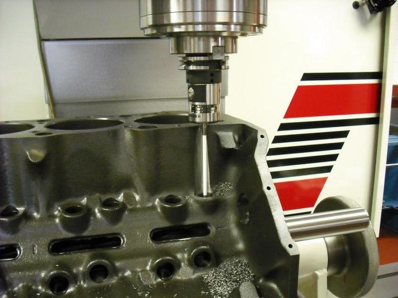
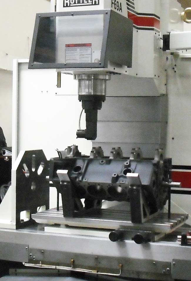
CNC engine block blueprinting begins by making very accurate measurements of the existing cylinder bore, lifter bore and deck location compared to the blueprint locations so corrections can be made. Our CNC Engine Block blueprinting machine is equipped with the Renshaw probe which automatically locates and measures cylinder bores (diameters, locations and angles), deck heights, and lifter bores with the factory blueprint.
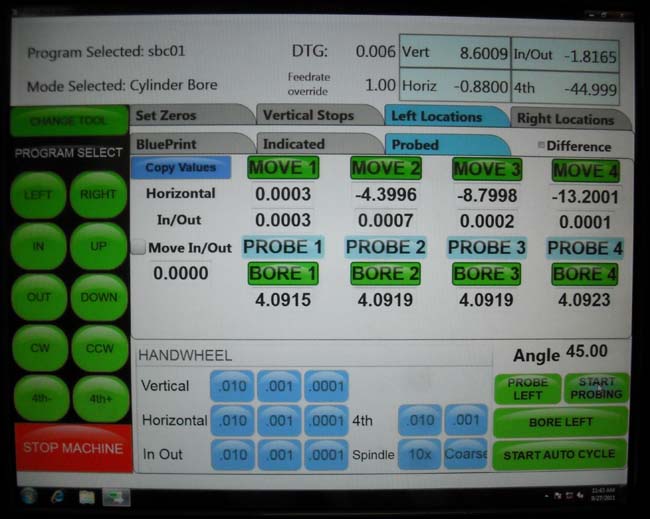
Our Master machinist runs the automatic CNC probe routine comparing the entire block blueprint with the probed locations. The CNC Control displays the actual diameters and positions of the cylinder bores, lifter bores, deck heights and compares it to the factory specs. The operator then chooses to make any modifications necessary in order to maximize the maximum blueprinted specifications.
CNC Probing Engine Blocks Blueprinting
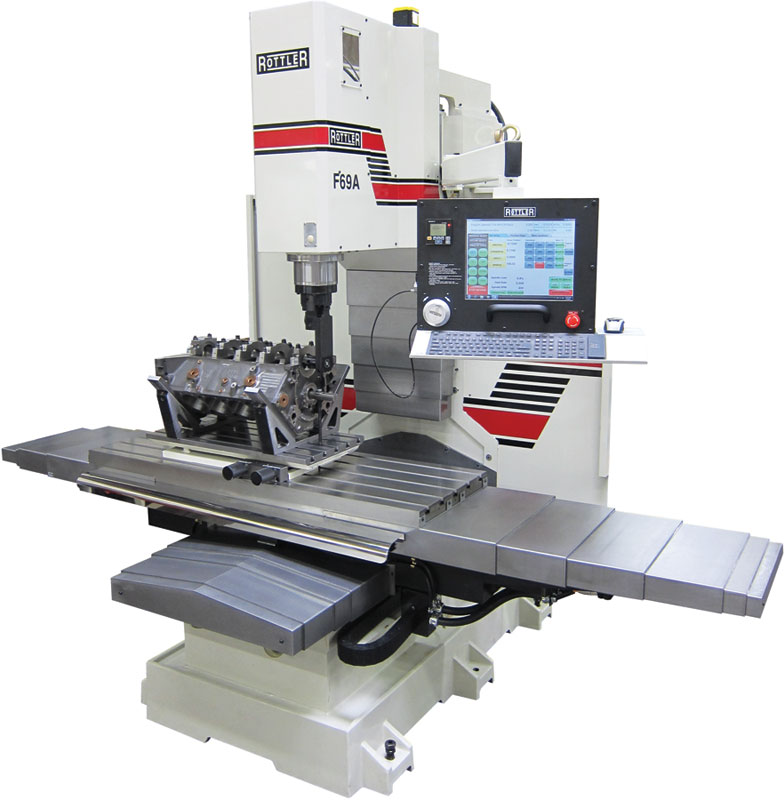
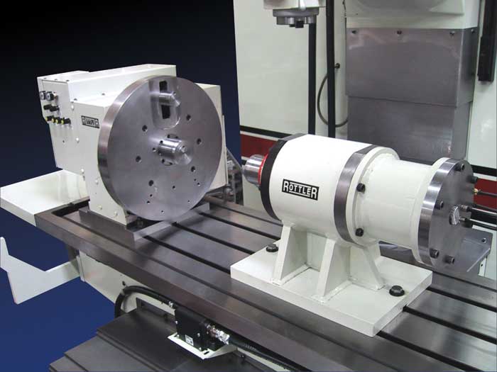
Rottler F69A CNC Engine Block Blueprinting & CNC Machining Center
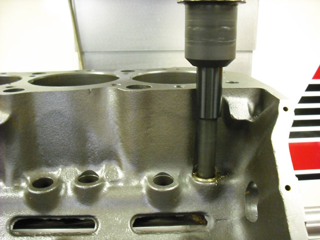
CNC Lifter Bore Correction ,Sleeving and Blueprint: Probing Routine.The CNC Probing Routing Verifies the lifter bores to the exact diameter, blueprint location and angle so corrections can be made to their position in an engine block front-to-rear and up-and-down, as well as to restore the correct lifter bore angle as referenced from the cam-crank centerlineNC Lifter Bore Correction ,Sleeving and Blueprint: Probing Routine.The CNC Probing Routing Verifies the lifter bores to the exact diameter, blueprint location and angle so corrections can be made to their position in an engine block front-to-rear and up-and-down, as well as to restore the correct lifter bore angle as referenced from the cam-crank centerline
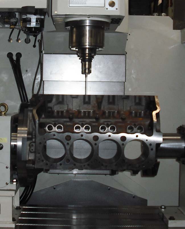
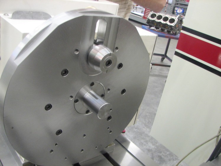
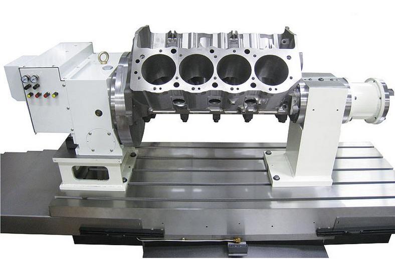
CNC Engine Block blueprinting starts with the CNC Probing routine. The routine compares the engine blocks blue print locations against the block specific blue print data. The Fourth Axis 360 Degree Rotate fixture utilizes Precision Datum and Rings that locate from the Main and Camshaft centerlines. CNC line boring will correct the main centerline. The block decks and cylinder bores are corrected to the crankshaft and camshaft centerline. The cylinder bores are bored on the blueprint center distances to blueprint specs. This process is achieved through the use of the 4th Axis 360 degree rotating fixture that references the crankshaft and camshaft centerline at a true 45 degrees. The block is probed from the centerline then indicated from the dowel location. This enables the bore spacing to be corrected and blue printing the deck surfaces square to the camshaft and crankshaft centerline at a true 45 degree angle is achieved. The dimensions are imputed to the CNC control holding tolerances to 0001. The Engine Block Blueprinting accuracy is achievable with CNC machinery and specialized Datum plates, and tooling along with the CNC Engine Block Blueprinting probe routine.
CNC Lifter Bore Correction ,Sleeving and Blueprint
Machine lifter bores to the exact diameter, location and angle.True up the stock size and location or bore complete new diameter, location or angle. The Rottler F69A CNC Machine enables R & L Engines to re-machine the lifter bores and correct their position in an engine block front-to-rear and up-and-down, as well as to restore the correct lifter bore angle as referenced from the cam-crank centerline. Rottler F69A CNC Engine Block Blueprinting machine utilizes the Renshaw Probe with the lifter blueprinting program to positions the precise blueprinted lifter bore location and angles.
CNC Engine Block Line Boring
Our Rottler F69A CNC Engine Block Line Boring process utilizes the right angle drive line bore cutter head. This virtually eliminates bar sag found on traditional line boring machines. The end results is perfect alignment with round and straight main line bores.
CNC Engine Block surfacing.
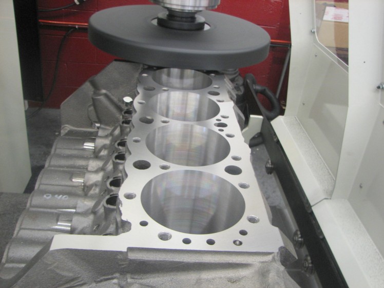
CNC Engine Block squaring will surface the block to the exact deck height specified. The probe automatically detects the block existing surface height at multiple locations so the operator can choose the proper surface depth to machine to for a perfectly flat and square deck to the cylinder bore. CNC block surfacing tooling included CBN and PCD tooling produces the exact RA surfaces finishes for superior gasket performance.
Unmatched Accuracy for 'TRUE' Cylinder Block and Head Blueprinting
All dimensions held to +- .0001
Boring and Sleeving of Blocks
M.I.D. Sleeve Kits Installed w/ Unmatched Accuracy, and NO LEAKING!
'Flanged" Sleeves Installed w/ Precision
True 'Square" Decking in Relation to the Main and Cam Bearing Saddles.
Precision Block & Head O-Ringing
Precision Main Bore Align Boring
4-Bolt Main Conversion Caps Installed
Stroker Crank and Rod Block Clearancing
CNC Engine Block Blueprinting


